
Cooling
CRAC vs. CRAH Units: Decoding the Air-Handling Alphabet
CRAC and CRAH units are the workhorses of traditional air-cooled data halls. Here is what the acronyms mean and how the two differ.

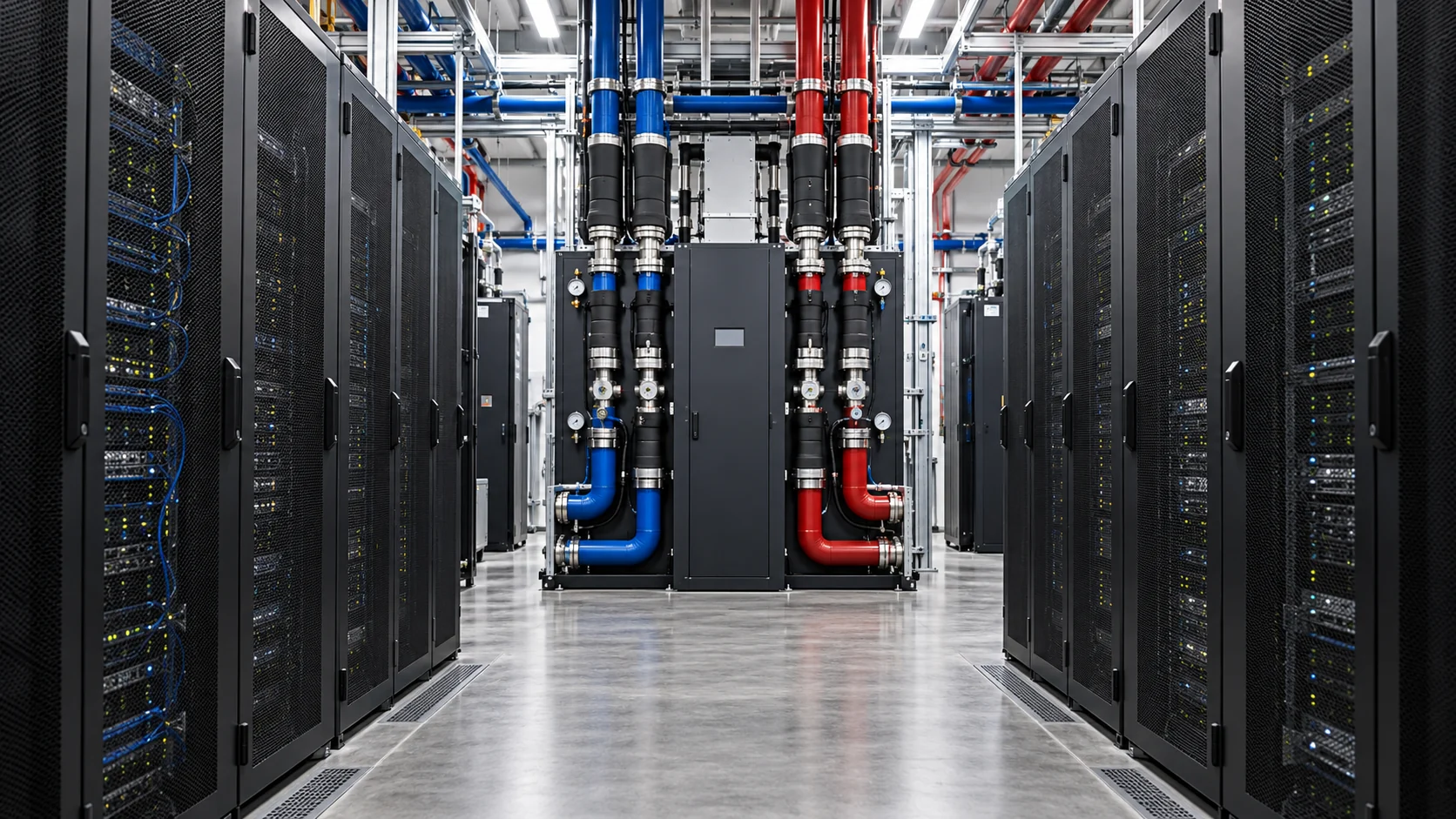
Spend time around data center engineers and you will hear a pair of acronyms that sound almost identical: CRAC and CRAH. Both refer to the big cooling cabinets that line the walls of many traditional data halls. They do similar jobs, but in different ways, and knowing the difference helps explain how a facility’s cooling plant is put together.
CRAC: computer room air conditioner
A CRAC unit is essentially a self-contained air conditioner designed for a computer room. It has its own refrigeration cycle inside: a compressor, an evaporator coil, an expansion device and a connection to a condenser. Warm room air passes over the cold evaporator coil and leaves cooler. The heat absorbed by the refrigerant is carried to a condenser, often outdoors, where it is released.
CRAC units are common in smaller and older facilities because they do not require a central chilled water plant. Each unit makes its own cooling.
CRAH: computer room air handler
A CRAH unit has no compressor. Instead, it contains a coil filled with chilled water supplied by a central plant of chillers, cooling towers or economizers. Fans push warm room air across the coil, the water absorbs the heat, and the warmed water returns to the plant.
CRAH units are common in larger facilities, where a central plant can produce chilled water efficiently for the whole building. They also pair well with economizers, since the central plant can use free cooling when outdoor conditions allow.
Comparing the two
- Where cooling is made. A CRAC makes cooling inside the unit. A CRAH relies on a central plant.
- Scale. CRACs suit smaller rooms and distributed setups. CRAHs suit larger buildings with central plants.
- Efficiency. Central chilled water plants with economizers can be very efficient at scale, giving CRAHs an advantage in big facilities.
- Maintenance. CRACs have refrigeration components in each unit, which means more distributed maintenance. CRAHs concentrate the complex equipment in the central plant.
- Redundancy. With CRACs, each unit is fairly independent. With CRAHs, the central plant and its piping need their own redundancy.
Other air-handling equipment
The air-handling family includes more members. In-row coolers sit between racks and cool air close to the equipment, which helps with higher densities. Fan walls are large arrays of fans and coils that move big volumes of air in hyperscale buildings. Overhead units and rear-door coils handle specific layouts.
Still relevant in the liquid era
As AI pushes facilities toward liquid cooling, air handlers still matter. Most liquid-cooled halls still have some heat in the air from memory, storage, networking and power supplies, and people working in the room need comfortable conditions. In hybrid facilities, CRAH units and chilled water systems often work alongside coolant distribution units, sharing the same central plant.
So the next time you see CRAC or CRAH on a floor plan, you will know the difference. One makes its own cold. The other borrows it from a plant down the hall.
Cooling
Liquid-Cooling Leak Detection and Reliability
Liquid cooling can unlock dense AI racks, but reliability depends less on the promise of water near electronics than on disciplined detection, isolation, testing, and maintenance.
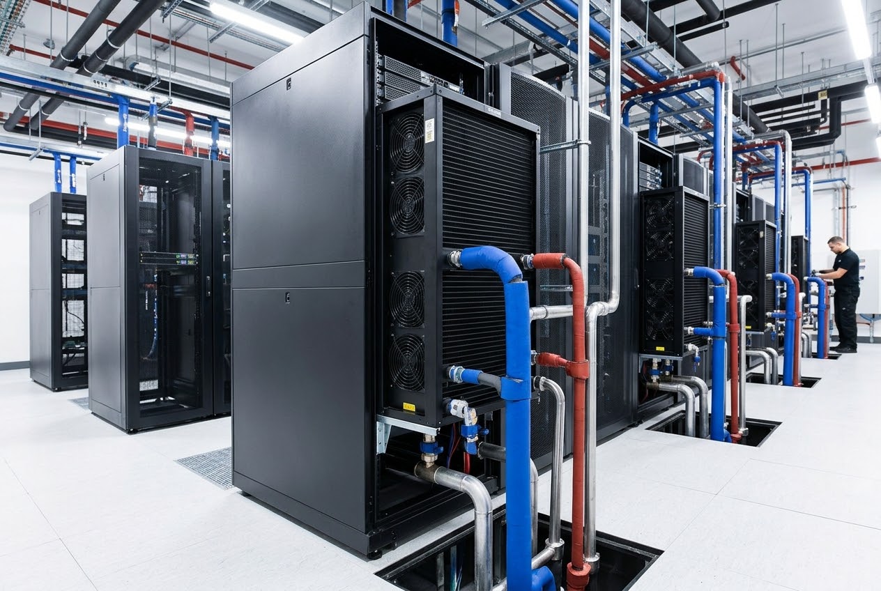
Liquid cooling is becoming ordinary infrastructure for high-density AI. It is also one of the easiest parts of the design to oversimplify. A cooling loop does not fail only when a pipe bursts. It can fail through a loose quick disconnect, a worn gasket, a cracked manifold, a blocked filter, a control error, condensation, or a slow seep that is discovered only after equipment has been exposed.
The reliability question is therefore not whether liquid cooling leaks. Every mechanical system has a leak risk. The question is whether the system is designed to detect a leak early, isolate it without losing an entire row, and keep water away from energized electronics.
Map the liquid boundary
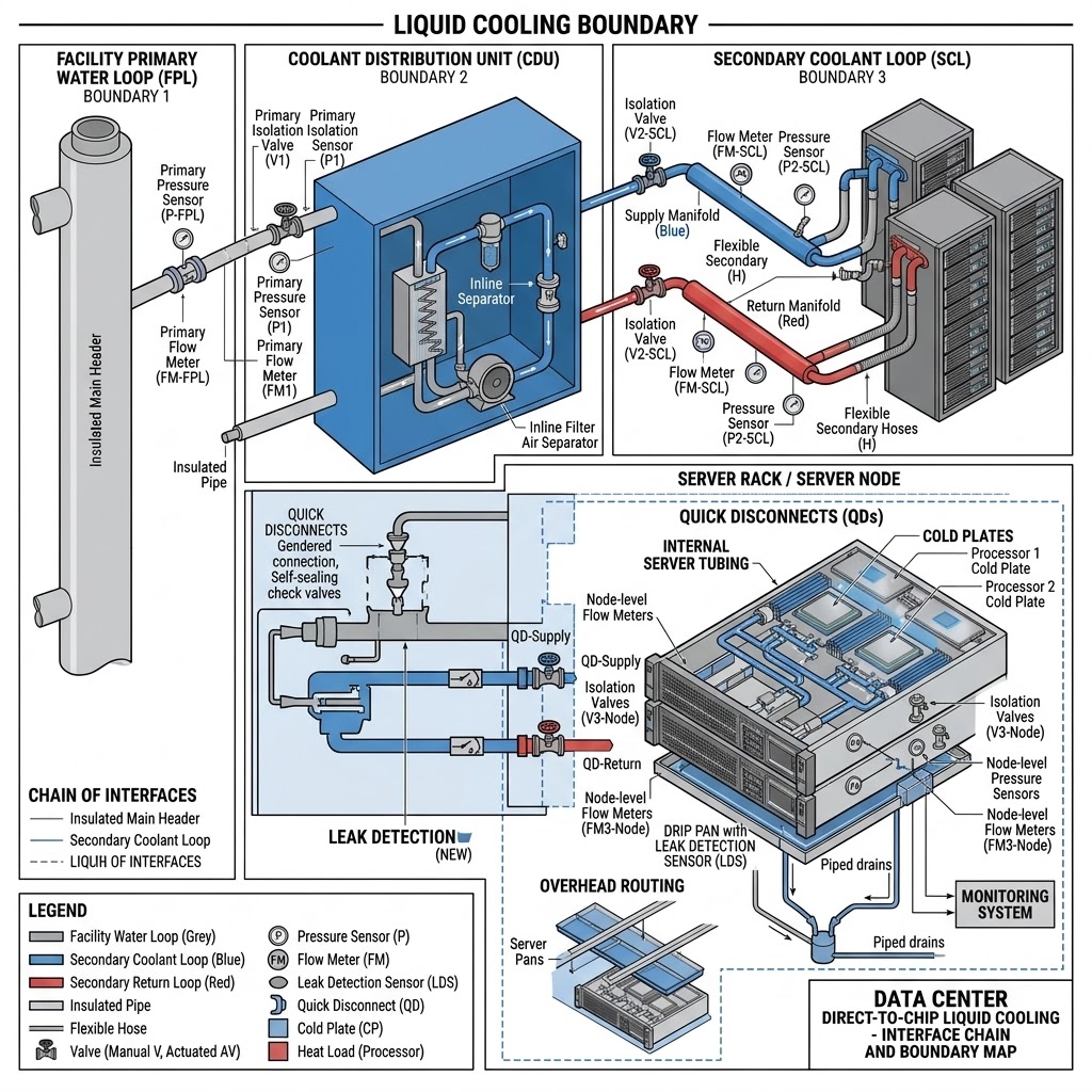
A direct-to-chip system usually has several boundaries: the facility water loop, a coolant distribution unit, secondary hoses or manifolds, cold plates, quick disconnects, and sometimes internal server tubing. Each boundary has different pressure, chemistry, temperature, and service procedures.
The first step is a component-level map. The operator should know the normal pressure and flow at every important segment, the locations of isolation valves, the drains, and the sensors. A “liquid-cooled rack” is not one component. It is a chain of interfaces.
ASHRAE’s guidance on liquid cooling recommends drip pans, leak detection, and piped drains where piping passes over critical equipment. The principle is straightforward: do not rely on a technician seeing a puddle. Put a sensor and a controlled path under the places where liquid could reach a server.
Detection should be layered
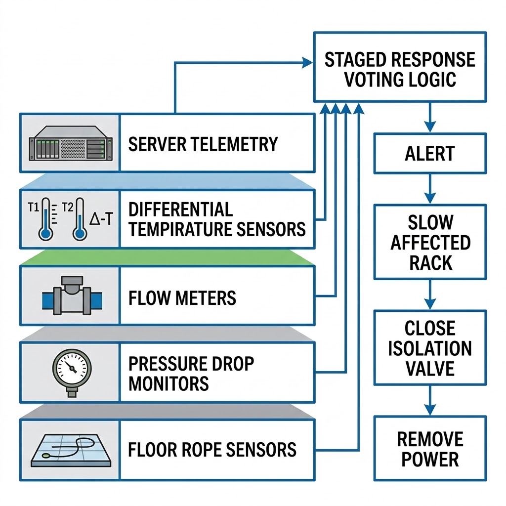
A reliable system combines different signals. Rope or spot sensors can detect liquid at the floor or in a drip tray. Pressure sensors can identify a rapid drop. Flow meters can reveal a pump or valve problem. Differential temperature can identify a cold plate that is not receiving the expected coolant. Server telemetry can show rising component temperatures before a leak becomes obvious.
No one sensor should be the only trip signal. A false alarm can interrupt an AI job; a missed alarm can damage equipment. Controls should use voting logic or staged responses where appropriate: alert, slow the affected rack, close an isolation valve, and then remove power if the evidence is strong.
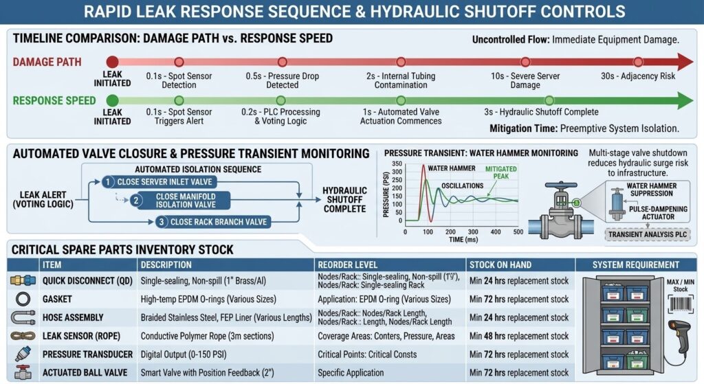
The response must be faster than the damage path
Early detection has value only if the operator has a defined response. The sequence should state who receives the alarm, which valve closes, how much coolant remains in the isolated section, and whether the rack can be serviced without taking adjacent racks offline.
A typical response may include stopping the local pump, closing supply and return valves, reducing IT power, and allowing the rack to coast down. The exact sequence depends on the equipment. A high-speed automatic shutoff may protect one rack but create pressure transients if it closes too quickly. Controls engineers must test the hydraulic behavior rather than assume that “closed” means “safe.”
Facility teams should keep replacement quick disconnects, gaskets, hoses, sensors, and pump components in stock. A leak response that waits for an international part can turn a small event into an extended capacity loss.
Water chemistry matters
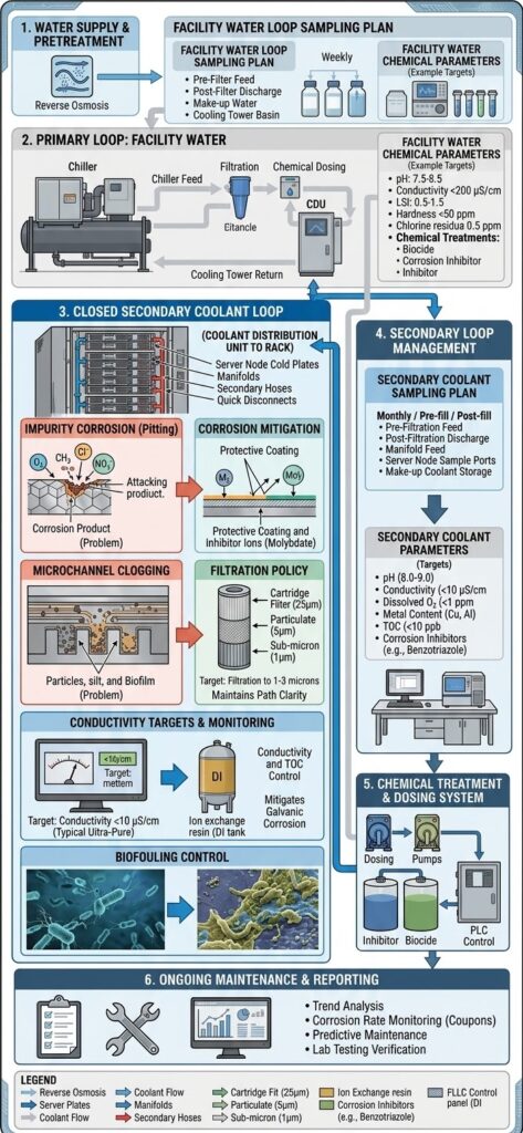
Coolant should be treated as an electrical and mechanical design input. Impurities can accelerate corrosion, clog microchannels, or damage seals. Inadequate treatment can shorten the life of cold plates and heat exchangers. Over-treatment can also create compatibility problems.
The operator needs a sampling plan, conductivity targets, filtration policy, microbiological controls where relevant, and a record of additions or flushes. The plan should identify which loop is being tested. Facility water and secondary coolant are not necessarily the same fluid.
Condensation is a separate risk
A leak is liquid escaping from the loop. Condensation is water forming on a surface because the surface is colder than the surrounding air’s dew point. A system can be leak-free and still create moisture if the coolant temperature is set too low or humidity control fails.
The safe design sets a minimum supply temperature or dew-point margin and monitors room humidity. The control system should prevent a valve or setpoint change from pushing the loop below the safe margin. Startup and shutdown deserve special attention because air conditions can change faster than water temperature.
Testing is part of uptime
Commissioning should include pressure testing, flow balancing, sensor calibration, alarm testing, valve isolation, and simulated fault response. The test should cover a slow leak, a fast pressure drop, a failed pump, a closed valve, a blocked filter, and a loss of communications.
The team should repeat critical tests after maintenance. A quick disconnect that was reconnected is not automatically good because it clicked into place. Inspect, pressure-test, and record it.
NVIDIA’s DGX Vera Rubin NVL72 documentation describes leak detection as a protection for equipment, data integrity, reliability, and safety. It also shows how the next generation of AI racks combines high power with liquid-cooled bus bars and manifolds. In other words, leak detection is not a luxury added after the rack is designed; it is part of the rack’s operating architecture.
A good reliability metric is recoverability
Operators often focus on whether a leak happened. A better metric is the size and duration of the resulting outage. Can one rack be isolated? Can a technician replace a component while the rest of the row runs? Are alarms visible in the same operations center as power and fire alarms? Can the organization prove that staff practiced the response?
Liquid cooling can be highly reliable when the system is designed as industrial infrastructure instead of treated as a plumbing accessory. The winning design keeps the liquid boundary visible, instrumented, segmented, and serviceable. That is what makes high-density AI practical.
Sources
- ASHRAE, “Emergence and Expansion of Liquid Cooling in Mainstream Data Centers”: ashrae.org
- NVIDIA, “DGX Vera Rubin NVL72 User Guide: Hardware,” accessed October 2026: docs.nvidia.com
- Vertiv, “How Rear-Door Heat Exchangers Support High-Density Rack Cooling,” 2025: vertiv.com
- U.S. Department of Energy, “United States Data Center Energy Usage Report 2025 Update,” 2025: energy.gov
- IEA, “Energy and AI,” April 10, 2025: iea.org
BOSSTOX Research articles are drafted with AI assistance and reviewed by our editors before publication. See our editorial standards.
Cooling
Rear-Door Heat Exchangers Explained
A rear-door heat exchanger is a practical middle step between all-air cooling and liquid-cooled servers, taking heat out at the rack without replacing every server in the room.

AI hardware has pushed many data centers beyond the point where air alone is comfortable. A rear-door heat exchanger, or RDHx, is one response. It sits on the back of a rack and captures exhaust heat before that air returns to the room.
The technology sounds simple because the core idea is simple: move heat from hot rack exhaust into a water loop. The engineering question is how much heat the door can remove, how the water loop is controlled, and how the facility handles the remaining heat and the liquid connection.
The physical arrangement
In a conventional air-cooled rack, cool supply air enters the server fronts, passes across components, and exits hot at the rear. A rear-door heat exchanger replaces or attaches to the rear door. Fans or the server fans push hot exhaust through a coil. Water flows through the coil and carries heat away.
A passive door relies primarily on server airflow. An active door includes fans that add airflow or reduce the pressure burden on the servers. Active doors can provide more control, but they add electrical consumption and another set of motors and controls.
The door can be dry, using refrigerant or another heat-transfer method, or it can use chilled water. Chilled-water RDHx systems are common in high-density environments because water carries much more heat per unit volume than air.
Vertiv announced the global launch of its CoolLoop chilled-water RDHx for AI and high-performance computing applications in March 2025. The company said the product could support up to 80 kilowatts per rack and could operate as a standalone system or complement direct-to-chip liquid cooling. That number is a product rating, not a universal promise: actual capacity depends on inlet air temperature, water temperature, airflow, server layout, and control limits.
Why an RDHx is attractive
The main advantage is that it can address high-density racks without immediately replacing the entire server fleet or distribution system. A data center can deploy doors on selected racks while other rows remain air cooled.
That makes the technology useful for mixed environments. A legacy enterprise row may operate at 8 to 15 kW per rack, while a new AI row may need far more. The operator can add targeted heat removal where it is needed.
RDHx also reduces the amount of heat released into the room. That can lower the room’s cooling burden and preserve supply-air conditions for neighboring racks. It does not eliminate heat; it changes where the heat is captured.
Vertiv’s educational material cited a shift toward higher rack densities by 2025: racks below 10 kW represented 38% of installed capacity, compared with 47% in 2024; the 10-to-20 kW range represented 30%, and 20-to-30 kW represented 28%. These percentages describe the cited installed-capacity mix, not every data center. The direction is what matters: more racks are entering a zone where room air management becomes harder.
The water loop is the system
An RDHx is only as useful as the loop behind it. The facility needs pumps, heat exchangers, valves, filtration, controls, isolation points, and a heat-rejection system. The water temperature must remain low enough to absorb heat but high enough to avoid unnecessary chiller work.
A warmer water loop can sometimes reject heat more efficiently or allow economization, but it reduces temperature difference across the coil. A colder loop improves heat transfer but can raise chiller energy and condensation risk.
The design must also consider pressure. High pressure can increase the consequences of a leak. Poorly located connections can make service difficult. Drip trays, leak detection, automatic shutoff, and drainage are not accessories; they are part of the equipment-protection system.
RDHx versus direct-to-chip
Direct-to-chip liquid cooling places cold plates on processors and sometimes memory or power components. It captures heat at the source and can support extremely dense systems. It also requires compatible servers, manifolds, quick disconnects, facility distribution units, and a service model for liquid-connected equipment.
An RDHx does not require liquid inside the server. It is therefore easier to retrofit and can work with a broader range of equipment. Its limit is that it cools the air leaving the rack. If the hottest components are concentrated inside a very dense server, the rack may still need direct-to-chip or immersion cooling.
The choices are not exclusive. A row may use direct-to-chip for GPUs and an RDHx to remove residual heat from CPUs, memory, network cards, and power supplies. Vertiv’s product material describes this complementary use.
How to underwrite an RDHx project
The first metric is not the door’s maximum kW rating. It is the measured rack load at the intended water temperature and airflow. Ask for performance curves and test conditions.
The second metric is availability. What happens if the pump stops, a valve closes, a fan fails, or a door is removed for service? Can the rack throttle, continue briefly on room air, or trip safely? Does the facility have redundant pumps and isolated loops?
The third metric is maintenance. Doors add weight, hinges, hoses, controls, and a service process. Technicians need safe access and a plan for moving the door without stressing connections.
RDHx is valuable because it gives operators a middle path. It is more than a special door but less invasive than converting every server to liquid cooling. For AI sites, that flexibility can reduce the gap between a high-density rack design and the physical building that must support it.
Commissioning also exposes a common blind spot: the room may be designed for a door’s rated heat removal, but the cooling plant may not have enough pumping, heat-rejection, or control capacity to sustain every door at once. The acceptance test should run the intended rack mix under realistic outdoor conditions and confirm that supply temperature, flow, and alarms stay within limits.
Sources
- Vertiv, “Vertiv Announces Global Launch of Chilled-Water Rear Door Heat Exchanger,” March 18, 2025: vertiv.com
- Vertiv, “How Rear-Door Heat Exchangers Support High-Density Rack Cooling,” 2025: vertiv.com
- Vertiv, “Vertiv CoolLoop RDHx”: vertiv.com
- ASHRAE, “Emergence and Expansion of Liquid Cooling in Mainstream Data Centers”: ashrae.org
- IEA, “Energy and AI,” April 10, 2025: iea.org
BOSSTOX Research articles are drafted with AI assistance and reviewed by our editors before publication. See our editorial standards.
Cooling
Direct-to-Chip vs. Immersion: The Cooling Choice Is a System Decision
Direct-to-chip cooling is the nearer-term retrofit path for many AI halls, while immersion can handle high density with deeper changes to hardware, operations and service procedures.
Why air is under pressure
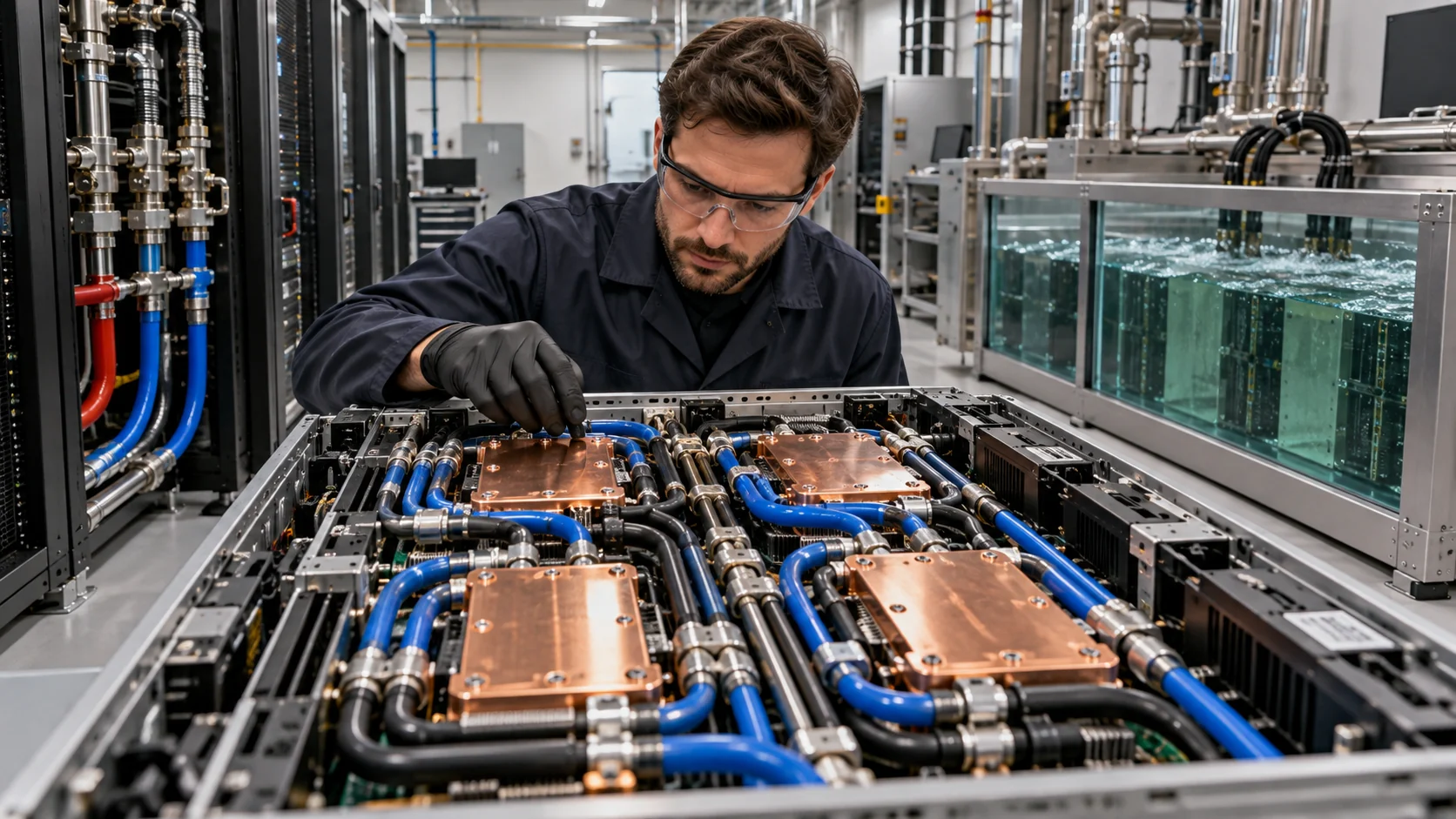
AI servers concentrate more heat in fewer racks. Traditional air cooling can work at moderate densities, but the fans, room airflow and heat exchangers become harder to scale as accelerators draw more power. Liquid carries heat more efficiently than air, which is why direct-to-chip and immersion systems are moving from specialty deployments into mainstream data-center planning.
The choice is not simply “which liquid is better.” It is a decision about server design, rack density, facility plumbing, service procedures, vendor support, operating temperature, capital cost and the ability to mix old and new equipment.
Direct-to-chip basics
Direct-to-chip cooling places a cold plate on the heat-generating component, commonly the GPU and CPU. A liquid loop moves heat from the cold plate to a coolant distribution unit, or CDU, which separates the technology loop from the facility water loop. The rest of the server may still use air.
This partial approach is why direct-to-chip can be attractive for a transition. It can remove most of the heat from the highest-power components while leaving storage, memory, power supplies and some networking on air. Vertiv describes direct-to-chip systems as using single-phase cold plates or two-phase evaporation units mounted on the board’s heat-generating components.
Direct-to-chip is not a single standard. Some designs use warm-water loops, some use chilled water, and some use refrigerants or two-phase fluids. The operating temperature determines how much free cooling the facility can use and whether a chiller is needed.
Immersion basics
Immersion cooling submerges servers or selected components in a dielectric fluid that does not conduct electricity. Single-phase systems keep the fluid liquid as it absorbs heat. Two-phase systems boil the fluid at a controlled temperature and condense the vapor back into liquid.
The biggest advantage is coverage. Immersion can cool more of the system and support high rack densities without forcing every heat source to have a separate cold plate. It can also reduce reliance on server fans and room airflow.
The tradeoff is that immersion changes the service environment. Operators need tanks, fluid management, filtration, lifting procedures, compatible materials, and a way to remove and service hardware. Some components, seals, cables, drives and warranty programs are not designed for submersion without qualification.
Density and retrofit
Direct-to-chip is often easier to insert into an existing facility because the data hall can keep some air infrastructure and use CDUs at the row or rack level. That does not make it plug-and-play. The floor, piping, leak detection, water treatment, power distribution and maintenance process still need to be engineered.
Immersion can be compelling in a new hall built around a stable hardware platform. A facility designed for tanks can optimize space, pump systems and heat rejection from the beginning. Retrofitting an air-cooled room for immersion can require more demolition and a new operating model.
The decision should start with the rack, not the cooling brochure. Ask what the rack will draw today, what it may draw in two years, which components are cooled by liquid and what happens when a customer uses a different server design.
Temperature and heat rejection
Liquid cooling can raise the temperature of the facility loop enough to increase the hours when dry coolers or economizers can reject heat without mechanical chilling. That can reduce compressor energy. It does not mean every liquid-cooled system is waterless or low-energy.
A CDU may transfer heat into a facility-water loop that still reaches a cooling tower. A dry cooler may eliminate evaporative water use but require more fan power on hot days. A two-phase refrigerant system may reduce water use while introducing fluid management and environmental considerations.
Vertiv and Intel reported a pumped two-phase direct-to-chip demonstration capable of dissipating up to 170 kilowatts of IT heat load while maintaining a maximum case temperature of 56.4 degrees Celsius at a flow rate of 0.48 liters per minute per kilowatt. That is a technology demonstration, not a universal performance guarantee, but it illustrates how the system should be measured: heat removed, flow, temperature and operating conditions.
What to measure
A serious comparison needs more than PUE. Track:
- Rack power density in kilowatts.
- Percentage of IT heat removed by liquid.
- Coolant supply and return temperatures.
- CDU efficiency and pump power.
- Water use effectiveness, or WUE.
- Mechanical cooling hours.
- Dry-cooler performance at peak ambient temperature.
- Leak incidents and mean time to repair.
- Hardware service time.
- Fluid replacement and disposal cost.
The business decision
Direct-to-chip usually wins when a customer wants high-density compute quickly, wants to preserve some standard service practices and expects the server platform to evolve. Immersion may win when density is extreme, the workload is stable, the facility is new and the operator can support fluid-based maintenance.
Neither is a universal answer. Mixed cooling can be rational: air for general-purpose racks, direct-to-chip for AI rows and immersion for the highest-density or edge cases.
BOSSTOX takeaway
Cooling should be evaluated as a chain from silicon to room to atmosphere. The right question is not whether direct-to-chip or immersion sounds more advanced. It is which system delivers the required thermal margin, serviceability, water profile and cost at a dated rack density.
There is also a failure-domain question. Direct-to-chip systems keep the coolant in a controlled circuit and can isolate a row or CDU, but a leak, pump failure or clogged cold plate can affect a large set of servers. Immersion reduces some air-flow and fan failure modes, yet a tank, fluid-quality problem or service mistake can affect every system in that tank. Operators should ask how failures are detected, isolated and repaired before comparing steady-state efficiency.
The customer’s refresh cycle matters too. A facility expecting to replace accelerators every twelve to eighteen months may value a cooling architecture that preserves standard server handling. A stable scientific-computing environment with long-lived hardware may accept immersion’s deeper integration. Cooling is therefore a deployment and operations decision, not only a heat-transfer decision.
Sources
- U.S. Department of Energy, “Cooling Water Efficiency Opportunities for Federal Data Centers,” January 9, 2019: energy.gov
- Vertiv, “Liquid and Immersion Cooling Options for Data Centers,” 2025: vertiv.com
- Vertiv, “Pumped two-phase direct-to-chip cooling,” 2025: vertiv.com
- U.S. Department of Energy, “Cooling Water Efficiency Opportunities for Federal Data Centers” — direct liquid cooling section: energy.gov
BOSSTOX Research articles are drafted with AI assistance and reviewed by our editors before publication. See our editorial standards.

The BOSSTOX App: Markets and the AI Build-Out on iPhone, iPad and Apple Watch

AI Server Rack Power Density, 2024-2027
The Life Cycle of a Data Center: Buildings Last Decades, Servers Do Not

Custom AI ASICs vs. GPUs

Gas Turbines on Data-Center Campuses

Transformer Lead Times Are Becoming a Data-Center Schedule Risk

GPU Supply Chains: How AI Hardware Gets Made, Moved, and Bottlenecked

Battery Storage at AI Sites
The BOSSTOX App: Markets and the AI Build-Out on iPhone, iPad and Apple Watch
AI Server Rack Power Density, 2024-2027
The Life Cycle of a Data Center: Buildings Last Decades, Servers Do Not
Custom AI ASICs vs. GPUs
-
 Power & Grid2 weeks ago
Gas Turbines on Data-Center Campuses
-
 Power & Grid2 weeks ago
Transformer Lead Times Are Becoming a Data-Center Schedule Risk
-
 Compute & Silicon3 weeks ago
GPU Supply Chains: How AI Hardware Gets Made, Moved, and Bottlenecked
-
 Power & Grid2 weeks ago
Battery Storage at AI Sites
-
 Cooling4 weeks ago
Water Use and Dry Coolers: The Tradeoff AI Sites Cannot Avoid
-

 Explainers1 month ago
Explainer: What an AI Inference Stack Actually Does
-

 Explainers1 month ago
AI Costs for Small Businesses: A Practical Model Before You Buy GPUs
-
 Compute & Silicon3 weeks ago
HBM Is a Bottleneck Because AI Memory Is a Stack, Not a Chip