
Networking
400G, 800G, 1.6T: What Network Speed Names Actually Mean
Network speeds in AI data centers keep climbing, with names like 400G and 800G. This explainer decodes the numbers, the lanes behind them and why each jump matters.

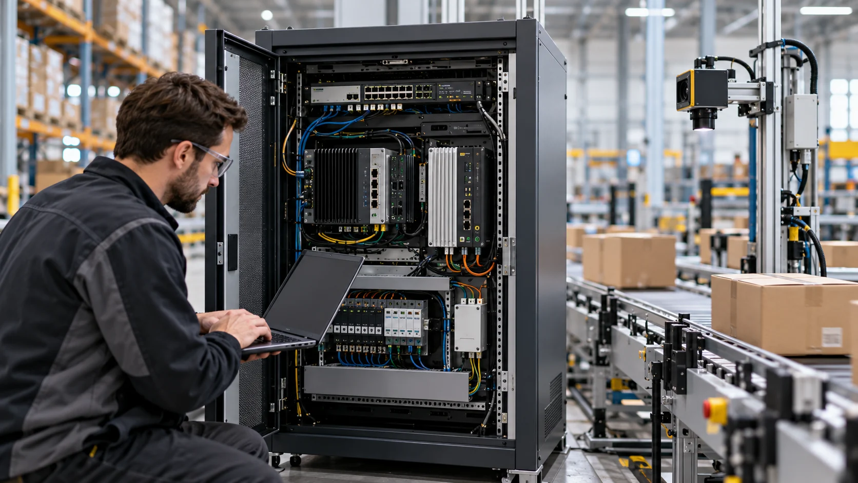
Coverage of AI networking is full of shorthand: 400G, 800G, 1.6T. These numbers describe the speed of individual network links, and the steady march from one to the next is one of the defining trends of the build-out. Here is how to read them.
The basic unit
Network speeds are measured in bits per second. G stands for gigabits per second and T for terabits per second. So 400G means 400 gigabits per second on a single port, 800G means 800 gigabits and 1.6T means 1,600 gigabits, or 1.6 terabits.
For comparison, a fast home fiber connection might be one or a few gigabits per second. A single 800G data center port can carry hundreds of times that.
Note that networks use bits, while storage and memory are often measured in bytes. One byte is eight bits, so an 800G link carries about 100 gigabytes per second at most, before overhead.
Lanes and SerDes
A high-speed port is not usually a single stream. It is built from several parallel lanes. An 800G port might use eight lanes of 100 gigabits each, for example. Each lane is driven by a circuit called a SerDes, short for serializer-deserializer, which converts parallel data inside the chip into a fast serial signal and back.
Faster speeds come from two levers: more lanes per port or faster lanes. Lane speeds have risen through successive generations, and each step requires new switch chips, new network cards, new transceivers and often new cables.
Modern high-speed links also use a signaling method called PAM4, which encodes two bits per symbol using four signal levels instead of two, doubling data rate at a given symbol speed, at the cost of being more sensitive to noise. Error correction compensates for the extra noise.
Why each jump matters
Moving to a faster speed generation can reduce the number of ports, cables and switches needed for a given amount of bandwidth, and it can let a switch of the same size connect more accelerators at full speed. For AI clusters, where each accelerator may need its own high-speed link and the fabric needs vast total capacity, those savings compound.
Each generation also raises challenges: more power per port, more heat in transceivers, shorter reach for copper cables and tighter manufacturing tolerances.
Standards and timing
Ethernet speeds are defined by the IEEE 802.3 working group, with industry groups often developing specifications for modules and implementations alongside. Products sometimes arrive before standards are fully finalized, and real deployments lag first announcements. It is useful to separate when a speed is demonstrated, when products ship and when it becomes common in large deployments.
Reading the numbers wisely
When you see a speed in a headline, ask whether it refers to a single port, a single accelerator’s total network bandwidth or a whole switch’s capacity. Those can differ by large factors. The steady doubling of port speeds is real and important, but its impact depends on how many links a system uses and how well the rest of the network keeps up.




Networking
Co-Packaged Optics Could Move the Network Bottleneck Into the Package
Co-packaged optics shortens the electrical path between a switch ASIC and optical engines, but it also makes packaging, testing and field service part of the networking decision.
The old link between switch and optics
In a conventional data-center switch, the switch ASIC sits on a board and connects electrically to pluggable optical transceivers at the front panel. The transceiver converts electrical signals to light and back again. This architecture is serviceable and familiar, but the electrical path gets harder to manage as SerDes speeds rise.
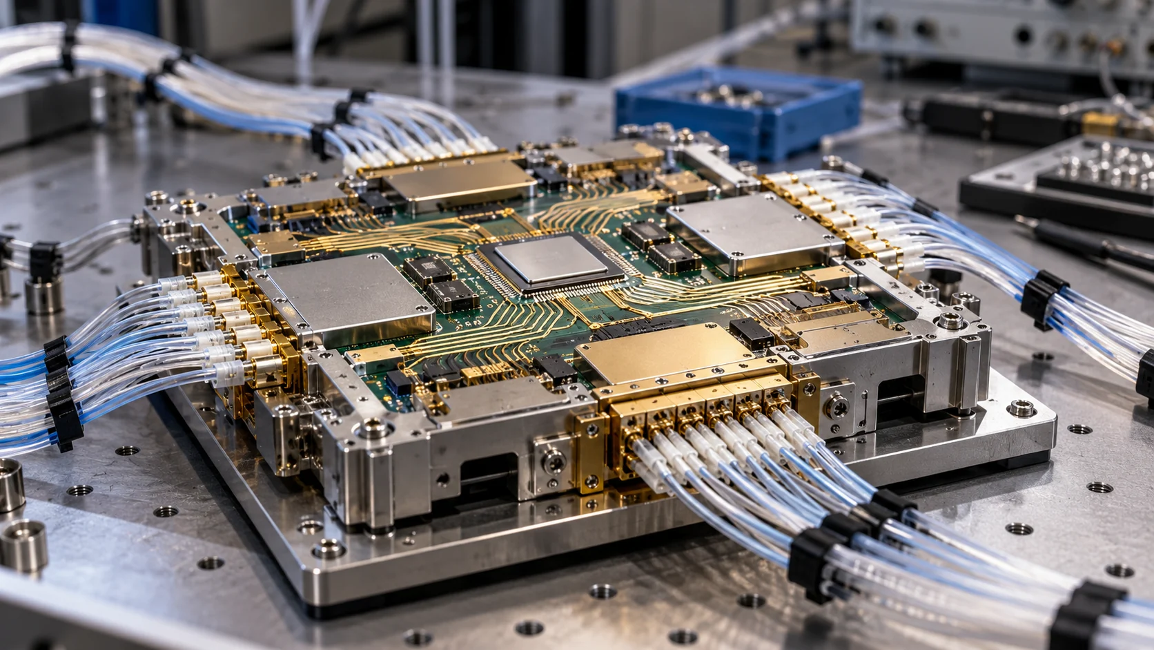
Co-packaged optics, or CPO, moves the optical engines closer to the switch ASIC on a common package or substrate. The shorter path reduces electrical loss and the power required to compensate for that loss. It can also increase bandwidth density around the switch.
Broadcom describes CPO as heterogeneous integration of optics and silicon on one packaged substrate. On its CPO materials, Broadcom claims more than 3.5 times power-consumption savings, 40% lower optics cost per bit and more than 1 terabit per millimeter of bandwidth density. Those are vendor claims tied to specific designs, so buyers should evaluate the test conditions rather than treat them as universal results.
Why AI makes the issue urgent
AI clusters create large scale-out and scale-up fabrics. Thousands of accelerators must exchange model parameters, gradients, activations and control traffic. A network link can become a performance limit if it cannot keep up with the compute fleet.
As electrical lane speeds move toward 200 gigabits per second and beyond, the board traces between a switch ASIC and front-panel modules consume more power and leave less signal margin. The optical module must compensate for the channel, often using a high-power digital signal processor. CPO reduces that electrical distance.
The benefit is not just headline bandwidth. Lower power per bit can reduce the heat that must be removed from the switch and the facility. A lower-loss path can also improve signal integrity and reduce the complexity of equalization.
The cost of integration
CPO turns optics into part of the switch package. That can make the switch more efficient, but it changes how the system is built and repaired. A failed optical engine may not be replaced like a front-panel module. The manufacturer must qualify the optical engine, silicon photonics, fiber attach, thermal path and package together.
The packaging line therefore matters. The same advanced assembly ecosystem used for AI accelerators may be relevant to optical switches. TSMC has described CPO work that integrates CoWoS modules with its photonics engine technology for high-end network switches. That is a reminder that compute packaging and network packaging are beginning to overlap.
The service model
Pluggable optics allow operators to replace an individual module when it fails or when a link standard changes. CPO can make the optical engine more tightly coupled to the switch, but it may require replacing a larger field-replaceable unit or sending the unit to a service center.
That can be acceptable in a tightly controlled hyperscale fleet. It is less straightforward in a multi-tenant colocation environment with varied optics, longer service contracts and customer-specific network designs.
CPO also raises questions about supply diversity. A pluggable ecosystem can mix modules from multiple vendors if they meet the standard. A CPO design may bind optics, switch silicon, package and firmware more closely. The efficiency gain can therefore come with greater vendor concentration.
Where CPO fits
CPO is most attractive where bandwidth density, power and scale are critical. It may be used in high-radix Ethernet switches, scale-up fabrics, or systems where front-panel power and electrical reach are limiting growth.
It is not automatically the right answer for every link. Short links may use copper or active electrical cables. Longer links may still favor pluggable optics because they are easier to upgrade. The architecture can be mixed inside one campus.
What to watch
For each CPO announcement, track:
- Switch bandwidth and lane rate.
- Optical engine technology and reach.
- Power per port or per terabit.
- Whether the product is sampling or shipping.
- Repair and replacement procedure.
- Package and test partner.
- Interoperability with the target network.
- Fiber-attach and yield constraints.
Broadcom’s 2025 optical-interconnect announcement described a 3-nanometer 200-gigabit-per-lane DSP and a 6.4-terabit-per-second optics attach for a custom AI accelerator. The important point is not just the number. It is the combination of optics, DSP, package, ASIC and network architecture.
BOSSTOX takeaway
CPO may solve an electrical-distance problem by creating a packaging and service problem. That does not make it a bad technology. It means the investment case should include the whole lifecycle: factory yield, optics qualification, power savings, field replacement and upgrade path.
The best CPO disclosure will state what is shipping, at what scale, with what power per bit and how the operator handles a failed optical engine. The package is becoming part of the network.
There is also a thermal tradeoff at the switch. CPO can reduce the electrical path and the power spent recovering signal quality, but it concentrates optics near a high-power ASIC. That creates a shared thermal environment in which the optical engine must operate reliably beside the switch silicon. The cooling system, package materials and optical alignment all become part of the network’s uptime story.
This is why early CPO deployments are likely to be selective. A hyperscale operator can standardize one switch, one optic and one service procedure across a large fleet. A smaller operator may prefer pluggables because the operational flexibility is worth more than the maximum power savings. The technology’s adoption curve will reflect service economics as much as raw bandwidth.
CPO also has an interoperability question. The optical engine may support an open electrical or optical interface, but the complete switch still depends on firmware, thermal controls, management software and diagnostic tooling. A buyer should ask whether the system can be monitored with the same telemetry used for pluggable optics and whether failed engines can be replaced without replacing the entire switch.
The adoption signal is therefore a combination of shipments, customer deployment and service data. Production CPO is meaningful. Production CPO with published power, failure and replacement statistics is much stronger evidence.
For operators, the question is not whether CPO will replace every pluggable optic. It is whether the package delivers a measurable advantage at the specific switch bandwidth and deployment scale. A smaller fleet may value service flexibility; a hyperscale fleet may value watts saved across thousands of ports.
In practice, that comparison should be made per rack and per deployment phase.
Sources
- Broadcom, “Co-Packaged Optics: Highest Power Efficiency and Bandwidth Density”: broadcom.com
- Broadcom, “Optical Interconnects for AI,” 2024: docs.broadcom.com
- Broadcom, OFC 2025 optical connectivity announcement: investors.broadcom.com
- TSMC, 2024 Annual Report, CoWoS and CPO discussion: investor.tsmc.com
BOSSTOX Research articles are drafted with AI assistance and reviewed by our editors before publication. See our editorial standards.
Networking
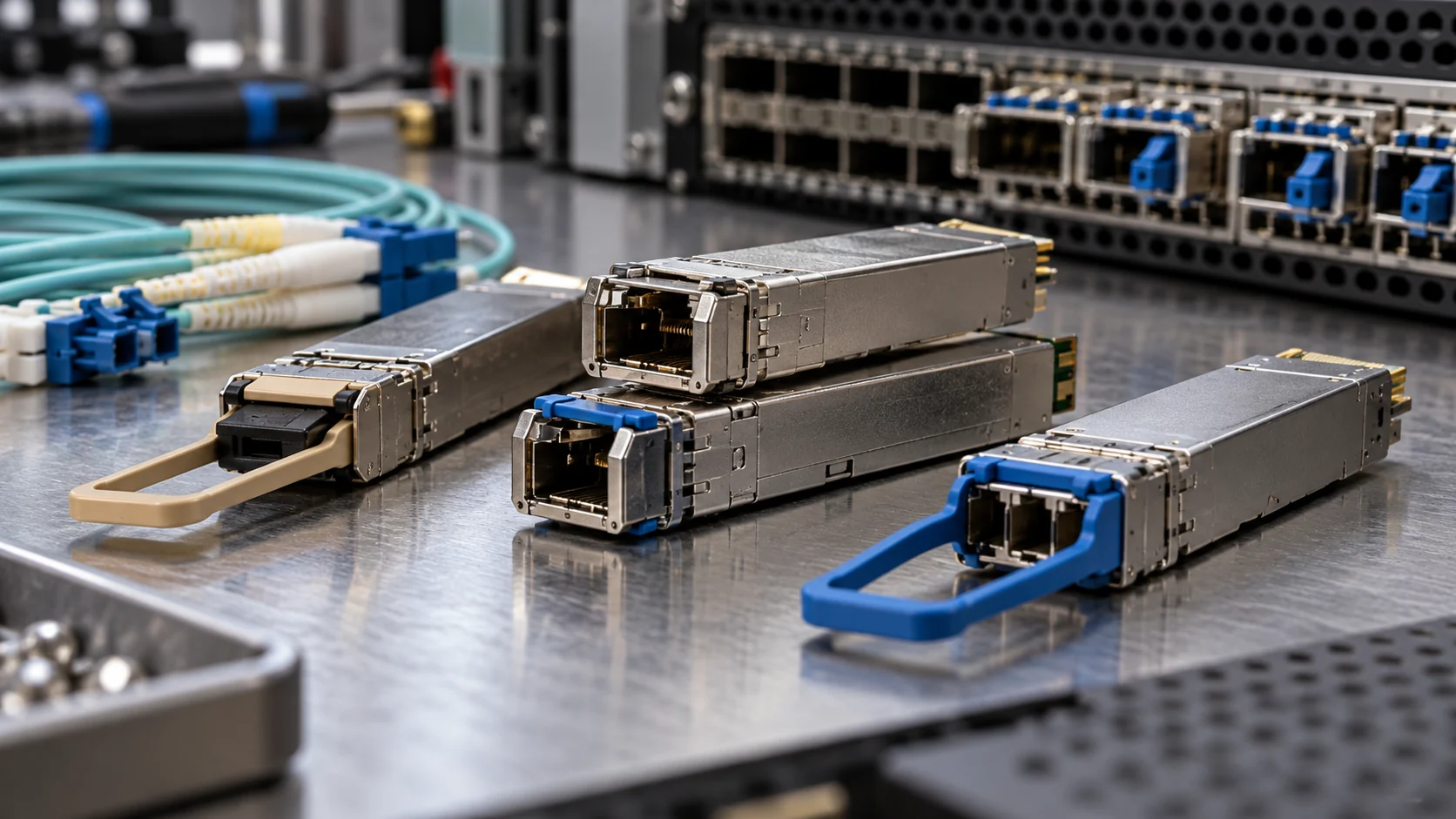
Why 800G and 1.6T Transceivers Matter to the AI Buildout
Faster optical transceivers are a response to rising switch and accelerator bandwidth, and their value shows up in link count, power, reach and network completion dates.
Bandwidth is a construction input
An AI data center can have enough floor space and enough GPUs but still fail to deliver useful throughput if the network cannot move data between them. Optical transceivers connect switches, servers and, in some cases, buildings or campuses. As the compute fleet grows, the network needs more links and each link needs more bandwidth.
An 800G transceiver can move 800 gigabits per second under the relevant interface specification. A 1.6T transceiver doubles that nominal rate. The numbers matter because they reduce the number of ports, fibers and switch stages needed for a given traffic load. They do not eliminate the need for careful topology, optics reach and congestion control.
What changed from 400G
AI clusters increase traffic in both scale-up and scale-out networks. Scale-up connects accelerators within a tightly coupled system. Scale-out connects racks and pods across a larger fabric. The optical requirements differ by distance, protocol, fiber type and error-correction scheme.
The move to 800G commonly uses multiple optical lanes. Broadcom’s 800G product materials describe 200-gigabit-per-lane PAM-4 technology and support for 800G DR4 and 1.6T DR8 pluggable designs. Coherent describes 800G as production-ready and 1.6T as the next step, with optical lanes moving from 100 gigabits per second toward 200 gigabits per second.
Higher speed can lower the amount of equipment required for a target bandwidth, but it can increase the engineering difficulty of each link. Signal integrity, laser performance, digital signal processing, fiber connectors, thermal limits and error correction all become more important.
The port-count math
Suppose a network needs 51.2 terabits per second of aggregate switching bandwidth. At a nominal 800G per link, it takes 64 links if the design were perfectly divisible and had no overhead. At 1.6T, it takes 32. Real systems include protocol overhead, redundant paths, uplinks, breakouts and spare capacity, so the final bill of materials is larger.
The example shows why transceiver speed can influence the whole system. Fewer physical links can mean fewer switch ports and less cabling. It can also mean fewer opportunities for link failure. But each transceiver may be more expensive, more power-hungry or harder to source.
Reach is part of the product
An 800G transceiver is not a single product. A short-reach multimode module, a 500-meter single-mode module and a multi-kilometer data-center-interconnect module use different lasers, fiber and thermal designs.
Coherent says AI-fabric Level 0 links are often below 50 meters, while links from top-of-rack to spine can reach up to 500 meters and longer router connections can run from 2 to 10 kilometers. The same 800G label therefore hides different products and supply chains.
Why 1.6T is not just a faster 800G
A 1.6T module often uses eight 200-gigabit-per-second lanes. That raises the demands on the host electrical interface, optical engine, DSP, thermal design and fiber connector. The module must also maintain an acceptable bit-error rate across the target reach.
The network may need new switch ASICs, new NICs, new cables and new test equipment. A data center cannot simply replace every 800G module with a 1.6T unit unless the switch, port, firmware and fiber infrastructure are compatible.
Power matters
Broadcom’s optical-interconnect material compares example power levels of 14 watts for an 800G pluggable and 25 watts for a 1.6T pluggable, while showing lower example values for CPO. Actual power depends on reach, temperature, DSP and form factor. Even so, optical power becomes a facility issue when a campus deploys hundreds of thousands of modules.
If a network has 100,000 800G modules at 14 watts each, the optics alone draw 1.4 megawatts before switch ASICs, servers and cooling. At 25 watts per module, the same count would draw 2.5 megawatts. The arithmetic is simple, but the planning implication is large: optics can move from a component line item to a measurable load.
What buyers should track
Track shipment dates, not demos. Broadcom announced a 3-nanometer 200-gigabit-per-lane PHY on August 27, 2025 for 800G DR4 and FR4 pluggable transceivers. Coherent’s product data for a 1.6T DR8 OSFP module lists an operating distance of 500 meters and an 8-by-200G PAM-4 architecture.
The relevant diligence questions are:
- Is the module in volume production?
- Which switch and NIC interfaces support it?
- What is the reach and fiber type?
- What is power at the target temperature?
- Is the module interoperable across vendors?
- How many modules are required for the planned cluster?
- Are lasers, DSPs and optical engines supply constrained?
BOSSTOX takeaway
800G and 1.6T transceivers matter because AI infrastructure is a bandwidth system. Faster links can reduce port count and cabling, but they also concentrate cost, heat and supply-chain risk into more complex components.
The best project model connects transceiver speed to rack count, switch count, fiber length, port power and commissioning dates. “The network is ready” should mean those links have been tested at the target protocol and workload, not merely that a product was announced.
The link budget should be modeled at the cluster level. An operator needs to know whether the module count grows with every accelerator, every switch, every redundant path or every building-to-building connection. It should also reserve spare modules and account for failures during commissioning. A 1.6T roadmap can reduce ports in the steady state but create an interim period where 800G and 1.6T equipment must interoperate.
The procurement risk is concentrated in specialized inputs. Lasers, DSPs, optical engines, connectors and test systems may each have different lead times. A network can therefore be “designed” months before the optics are actually available. Shipping the first module is a milestone; shipping enough tested modules to fill a production fabric is the milestone that changes capacity.
Sources
- Broadcom, 800G and 1.6T PAM-4 PHY product brief: docs.broadcom.com
- Broadcom, BCM83822 800G PHY, August 27, 2025: broadcom.com
- Coherent, “Datacom Innovation in the AI Era”: coherent.com
- Coherent, 1.6T-DR8 OSFP transceiver product page: coherent.com
- Broadcom, “Optical Interconnects for AI,” 2024: docs.broadcom.com
BOSSTOX Research articles are drafted with AI assistance and reviewed by our editors before publication. See our editorial standards.
Networking
Fiber for AI: Why Networks Inside and Between Data Centers Matter
Powerful accelerators sit idle if data cannot reach them. Fiber and the fabrics built on it decide how much of a cluster is actually usable.
Key points
- AI has two network problems: moving data inside a cluster, and moving it between sites and users.
- Inside the cluster, congestion, topology and collective-communication software matter as much as port speed.
- Redundancy is only real when two circuits do not share the same conduit or failure point.
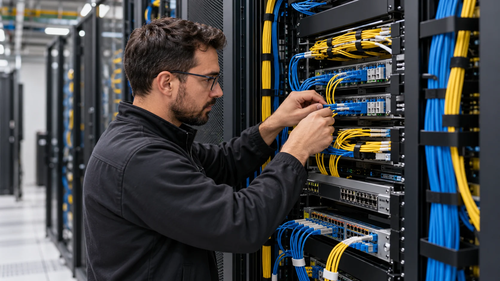
AI infrastructure is often pictured as a room full of GPUs. That picture is incomplete. The processors only perform well when the network can move data between them. Fiber is the long-distance and high-bandwidth plumbing that connects data centers to each other, to users, and to the wider internet.
Two different network problems
There are two different network problems. The first is inside a data center. During training, many accelerators work on the same model. They repeatedly exchange parameters, gradients, and activation data. During inference, a service may distribute requests across many machines and retrieve data from storage. These exchanges can become the bottleneck if the network is slower than the compute.
The second problem is between locations. A company may store data in one region, train a model in another, and serve users from several points of presence. A cloud provider may move traffic among data centers for capacity, resilience, or regulatory reasons. Those links need enough bandwidth and predictable latency to make the distributed system behave like one service.
Why fiber, and what rides on it
Fiber matters because it can carry very high data rates over long distances with low signal loss. In a data center, multimode and single-mode fiber may be used for different distances and designs. Optical transceivers convert electrical signals into light and back again. The transceiver, cable, switch, routing design, and software all affect performance.
AI clusters also use specialized fabrics. NVIDIA’s documentation distinguishes several networks in a modern AI data center: a tenant-facing network, a management network, a GPU cluster interconnect, and the high-bandwidth links that connect GPUs within a rack. This separation exists because the traffic has different timing, security, and reliability requirements.
The cluster fabric
The internal cluster network is particularly important for distributed training. If one accelerator finishes its work and waits for data from another, the whole job can slow down. The problem is not simply the advertised port speed. It includes congestion, buffer behavior, topology, routing, collective-communication software, and the ratio between compute and communication.
Latency matters more for interactive inference. A user does not experience a model as a spreadsheet of total throughput. They experience the delay before the first token and the rate at which the rest of the answer appears. A network path that crosses multiple regions may add latency even when it has ample bandwidth.
Resilience is physical
Fiber is also a resilience issue. A single physical route can be cut by construction, weather, or an accident. Critical sites need diverse entrances and separate paths. A company should understand whether two different circuits actually share the same conduit or carrier hotel. Redundancy is real only when a single failure does not take out both paths.
The edge-computing conversation is partly a network conversation. Moving inference closer to the user or device can reduce round-trip delay and limit the amount of raw data that must travel to a central region. It does not eliminate the need for a backbone. Models, updates, logs, and aggregated data still move through the network.
Choosing a network for the workload
For businesses, the right network decision depends on the workload. A batch analytics job may tolerate delay and prioritize lower transfer cost. A voice assistant or industrial control system may require consistent latency. A retrieval system may need fast access to a document store. A multi-tenant AI platform may need strict isolation between management traffic and customer data.
The practical questions are straightforward. Where is the data generated? Where is the model served? How much data must move for each request? Is the workload sensitive to first-byte latency, sustained throughput, or both? What happens if one link fails? Are the model artifacts and customer data encrypted in transit? Can the provider show actual performance rather than only theoretical port speeds?
Fiber is not glamorous, but it determines how much of a data center’s compute capacity can be used. A cluster with powerful accelerators and a weak interconnect can behave like a traffic jam of expensive machines. A well-designed network turns the processors into a coordinated system.
As AI grows, network architecture will become part of application architecture. The model, the hardware, the data store, the fiber path, and the user experience cannot be designed separately if the goal is predictable performance.
What BOSSTOX is watching
- Optical transceiver supply as cluster sizes grow.
- Diverse fiber routes into new AI campuses.
- Measured, not theoretical, latency figures from providers.
Sources
- NVIDIA, Data Center Architecture
- NVIDIA, NVLink and AI-factory networking
- Federal Communications Commission, Measuring Broadband America
BOSSTOX Research articles are drafted with AI assistance and reviewed by our editors before publication. See our editorial standards.

The BOSSTOX App: Markets and the AI Build-Out on iPhone, iPad and Apple Watch

AI Server Rack Power Density, 2024-2027
The Life Cycle of a Data Center: Buildings Last Decades, Servers Do Not

Custom AI ASICs vs. GPUs

Gas Turbines on Data-Center Campuses

Transformer Lead Times Are Becoming a Data-Center Schedule Risk

GPU Supply Chains: How AI Hardware Gets Made, Moved, and Bottlenecked

Battery Storage at AI Sites
The BOSSTOX App: Markets and the AI Build-Out on iPhone, iPad and Apple Watch
AI Server Rack Power Density, 2024-2027
The Life Cycle of a Data Center: Buildings Last Decades, Servers Do Not
Custom AI ASICs vs. GPUs
-
 Power & Grid2 weeks ago
Gas Turbines on Data-Center Campuses
-
 Power & Grid2 weeks ago
Transformer Lead Times Are Becoming a Data-Center Schedule Risk
-
 Compute & Silicon3 weeks ago
GPU Supply Chains: How AI Hardware Gets Made, Moved, and Bottlenecked
-
 Power & Grid2 weeks ago
Battery Storage at AI Sites
-

 Cooling4 weeks ago
Water Use and Dry Coolers: The Tradeoff AI Sites Cannot Avoid
-

 Explainers1 month ago
Explainer: What an AI Inference Stack Actually Does
-

 Explainers1 month ago
AI Costs for Small Businesses: A Practical Model Before You Buy GPUs
-
 Compute & Silicon3 weeks ago
HBM Is a Bottleneck Because AI Memory Is a Stack, Not a Chip