
Power & Grid
Baseload, Intermediate and Peaking Plants: How the Grid Fills a Day
Grid operators stack different kinds of power plants to match demand as it rises and falls through the day. Here is how the traditional categories work and how they are changing.

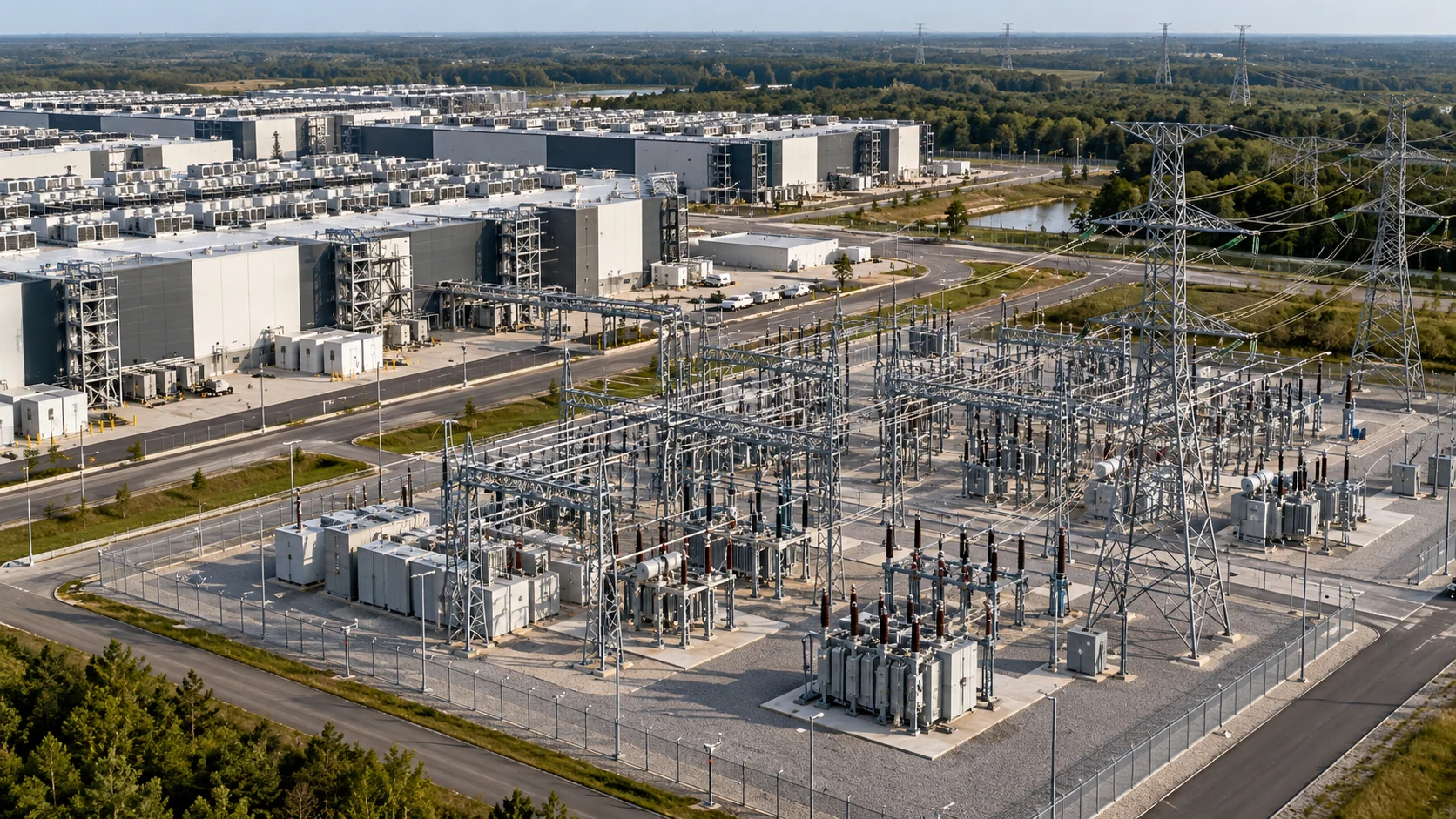
Electricity demand is never flat. It dips overnight, climbs through the morning, and peaks in the late afternoon or evening, with the exact shape depending on the season and the region. Grid operators have traditionally met that shifting demand by layering different types of power plants, each suited to a different part of the curve.
Baseload and intermediate plants
Baseload plants run most of the time and cover the minimum level of demand that exists around the clock. Historically these were large coal and nuclear plants. They have high upfront costs, relatively low fuel costs per unit of energy, and they work best running steadily rather than ramping up and down.
Nuclear plants remain the clearest example. They are designed for continuous operation and are generally kept running at or near full output.
Above the baseload sits a band of demand that rises and falls through the day. Intermediate plants follow that movement. Combined-cycle natural gas plants often fill this role because they are efficient and can adjust output more readily than older baseload units.
Peaking plants
At the top of the curve are the highest-demand hours, often on the hottest summer afternoons or coldest winter mornings. Peaking plants are built to start quickly and run for relatively few hours each year. Simple-cycle gas turbines and reciprocating engines are common peakers. They are less fuel efficient, but their ability to ramp fast makes them valuable when the system is under strain.
How dispatch decides who runs
In organized markets, operators generally call on resources in order of their offered price, starting with the cheapest. This is sometimes called the merit order or supply stack. Resources with near-zero fuel costs, like wind, solar and nuclear, tend to sit at the bottom. Higher-cost units are added as demand climbs. The last unit needed to meet demand at a given moment often sets the market price for that interval.
Why the old categories are blurring
The neat three-tier picture is changing:
- Wind and solar produce large amounts of low-cost energy when available, but their output varies with weather and time of day.
- Batteries can charge when power is plentiful and discharge during peaks, doing some of the work peakers once did.
- Gas plants increasingly ramp up and down to fill gaps left by variable resources.
- Demand response lets some customers reduce use during peaks, effectively acting as a resource.
Many grid planners now prefer terms like firm, flexible and variable over baseload and peaking. Firm resources can be counted on when needed. Flexible resources can change output quickly. Variable resources produce when conditions allow.
What this means for large new loads
A data center adds demand at every hour, which raises the floor of the daily curve rather than just the peaks. That pushes operators to think about firm, around-the-clock supply. It also raises a newer question: whether some computing loads can flex their demand during the tightest hours, helping the grid much as a peaking plant would. How that develops will shape how much new generation each region needs.
Watching a Single Day Unfold
A simplified picture of a hot summer weekday shows how the layers stack up in a region with a typical mix of resources.
- Overnight. Demand sits near its daily low. Nuclear units run steadily, wind contributes whatever the weather allows, and a few combined-cycle gas plants run at moderate output. Prices are usually low.
- Morning ramp. As people wake and businesses open, demand rises. Intermediate plants increase output, and solar begins to contribute as the sun climbs.
- Midday. Solar output is at its strongest. In solar-heavy regions, gas plants may throttle back, and batteries may charge from low-cost midday power.
- Late afternoon to evening. Air conditioning load remains high just as solar fades. This is often the tightest stretch of the day. Batteries discharge, peaking plants start and prices tend to rise.
- Night. Demand eases, peakers shut down and the system settles back toward its overnight pattern.
A winter day can look quite different, with sharp peaks before sunrise and after dark, which is why planners study both seasons carefully.
Why Different Plants Cost Different Amounts to Run
The layering is driven by economics as much as engineering. Two broad types of cost help explain the order:
- Fixed costs include construction, financing and staffing. They are paid whether the plant runs or not.
- Variable costs include fuel and some maintenance. They are incurred only when the plant produces power.
A plant with high fixed costs and low variable costs, like a nuclear unit, makes the most sense running as many hours as possible. A plant with low fixed costs and higher variable costs, like a simple-cycle turbine, makes sense sitting idle most of the time and running only when its output is most valuable. Intermediate plants sit between those extremes.
Common Misunderstandings
“Baseload” means “reliable”
The term describes how a plant is typically operated, not a guarantee of performance. Any plant can trip offline or be affected by extreme weather or fuel problems.
Peaking plants are wasteful
They are less fuel efficient per unit of energy, but because they run few hours, they can be a cost-effective way to cover rare high-demand periods. The alternative would be building more expensive plants that sit idle most of the year.
The merit order is fixed
The order shifts as fuel prices change, plants go into maintenance, weather affects renewable output and transmission congestion limits where power can flow.
Questions Readers Ask
What sets the price when renewables are on the margin? When low-cost resources can meet all demand, the marginal price can fall very low, and in some markets it can briefly go negative. When a gas plant is the last unit needed, its costs tend to set the price.
Can a data center act like a peaker in reverse? Some operators are exploring whether certain computing tasks can pause or move during tight hours. The concept is promising for flexible workloads but harder for latency-sensitive services.
Why do prices spike so sharply on extreme days? Near the top of the supply stack, each additional megawatt comes from progressively more expensive or scarce resources, so a small increase in demand can raise prices a great deal.
Are new plants still built to be baseload? Some are, especially firm resources intended to run around the clock. But many new projects are designed for flexibility, able to ramp quickly and run fewer hours, because that is increasingly what a grid with more variable resources needs.
Latest stories
View all


Power & Grid
A Maintenance Window Changes the Meaning of Redundancy
A facility’s normal arrangement is only one of its operating states. When equipment is removed from service for maintenance, the remaining paths may carry a different risk. A redundancy label needs to be read with that temporary configuration.
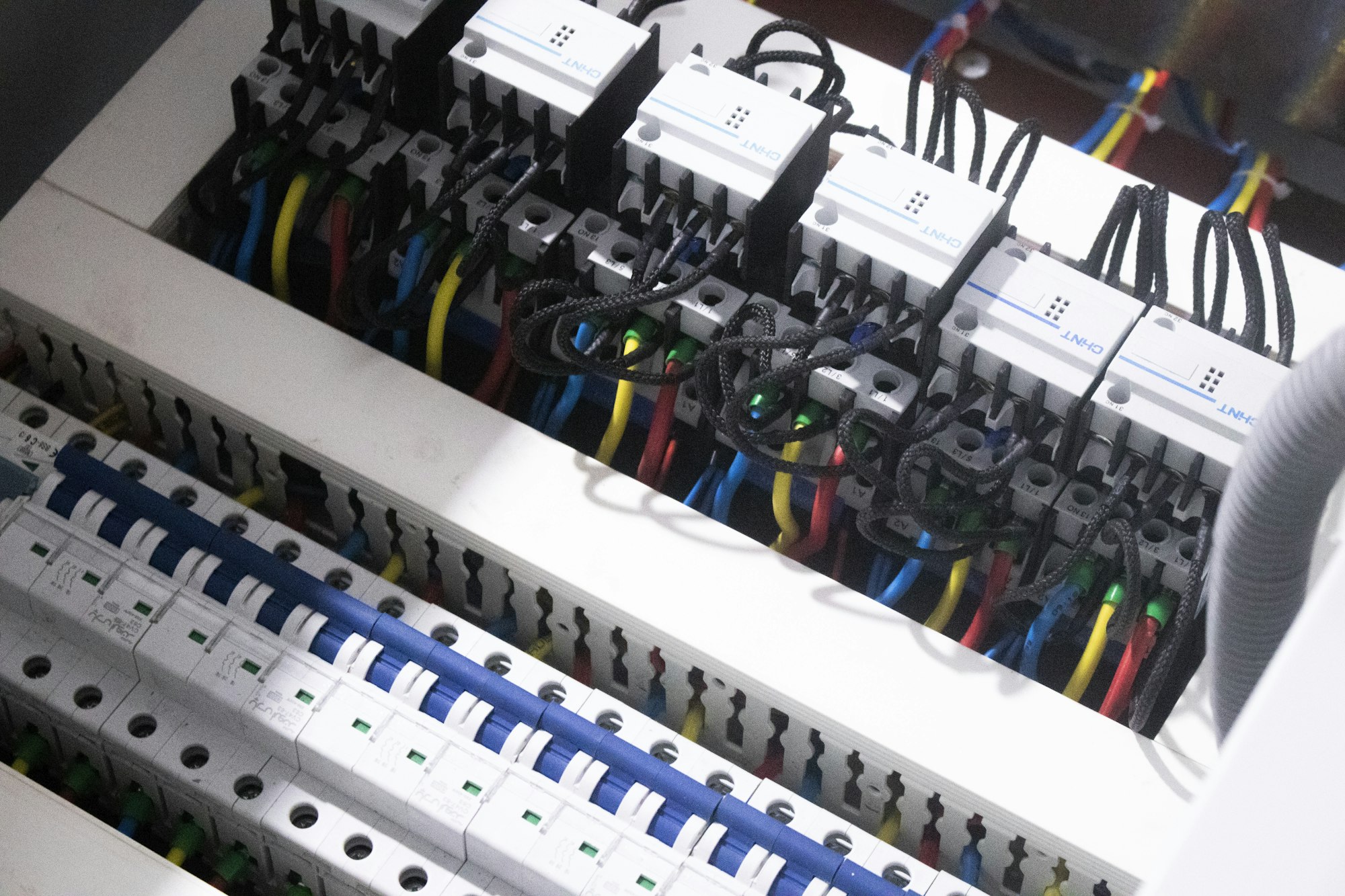
Photo: mostafa mahmoudi / Unsplash
A facility's normal arrangement is only one of its operating states. When equipment is removed from service for maintenance, the remaining paths may carry a different risk. A redundancy label needs to be read with that temporary configuration.
The operating distinction
Maintenance can remove a spare component, change a transfer path or increase the load on equipment that remains available. The operational question is which further interruption the system could tolerate in that state. That question may have a different answer from the one given for normal operation.
Temporary states deserve names that operators can recognize. If a system has several possible maintenance configurations, a generic instruction to use the backup can leave too much unstated. The arrangement being discussed should match the equipment actually removed from service.
A practical example
Imagine a hypothetical system with alternate power paths while both are available. During planned work on one path, the other becomes more important. A second task on a related component could create an exposure that neither maintenance activity would create alone.
Questions worth asking
The temporary configuration changes the relevant failure question. Describing the available paths during maintenance helps readers understand both why the work is necessary and which additional conditions the operating team must manage around it.
- What protection remains while the selected equipment is unavailable?
- Could another planned activity affect the same remaining support path?
- What condition would postpone the work or require restoration of the normal arrangement?
What the evidence supports
This does not mean that maintenance should be avoided. Deferred work can increase other risks. It means that timing, dependencies and contingency arrangements belong in the planning discussion. Only qualified personnel following the site's procedures should operate or isolate electrical equipment.
The communication record should also identify when the temporary condition begins and how normal status is restored. Otherwise the next shift may inherit a narrower margin without realizing it. In a public explanation, this can remain high-level: the purpose is to distinguish resilience under normal conditions from resilience during planned work, not to publish sensitive switching instructions or suggest that every maintenance activity creates the same risk.
Describe resilience during the actual maintenance state, rather than borrowing the normal-state label without qualification.
Quick check
How much did you catch? Tap a question to see the answer.
1. Why read a redundancy label alongside maintenance plans?
Answer: Taking equipment out of service changes the risk on the paths that remain.
2. What question matters during maintenance?
Answer: Which further interruption the system could tolerate in that temporary state.
3. Why is “use the backup” too vague?
Answer: It doesn’t say which configuration matches the equipment actually removed from service.
Thinking in Operating States
A helpful habit is to describe a system as a set of named operating states rather than a single design. Each state has its own available paths and its own answer to the question of which further failure it could tolerate. In general terms, a facility might move through states such as these:
- Normal. All designed paths and spare components are available.
- Planned maintenance. A specific component or path is intentionally out of service for work.
- Degraded after a fault. A component has failed unexpectedly and the system is running on the remaining paths.
- Testing. The system is deliberately placed in a configuration to confirm that a function works.
- Restoration. Work is complete and the system is returning to normal, but checks are not yet finished.
Describing which state applies, and what remains available in it, gives operators and readers a shared language. It also makes clear that the same facility can have different resilience at different times of the same week.
Planning a Maintenance Window Step by Step
The following outline describes how a planning discussion can be structured. It is not a switching procedure, which belongs to qualified personnel and site-specific methods.
- Name the affected equipment and resulting state. State clearly what will be out of service and what the remaining arrangement will be.
- Identify what remains protected. Describe which further faults the remaining paths could tolerate.
- Check for overlapping work. Review other planned activities, supplier visits and tests that could affect the same remaining path.
- Consider external conditions. Weather forecasts, utility notices and unusual load periods may favor a different timing.
- Set stop conditions. Agree in advance which developments would pause the work or trigger a return to the normal arrangement.
- Communicate the window. Inform affected teams and customers as appropriate, including start, expected end and restoration checks.
- Confirm restoration. Verify that normal status has returned and record it so the next shift knows.
Common mistakes
Two unrelated teams scheduling work on components that share a dependency is a classic problem, especially when change records are kept in separate systems. Another mistake is leaving a temporary state in place longer than planned without updating the shift record. A third is treating the restoration as complete as soon as equipment is energized, before checks confirm that the redundant path is genuinely available again.
What This Means for Customers and Readers
For a business hosted in a facility, maintenance notices are an opportunity to understand how resilience changes during planned work. A provider that explains the temporary state, the remaining protection and the stop conditions is communicating useful information. For readers following the industry, a redundancy label describes design intent; operating practice determines how well that intent holds up across the year.
Redundancy is a property of a particular moment, not a permanent label on the building.
Questions Readers Ask
Why not simply avoid maintenance to keep redundancy intact?
Deferred maintenance can increase the chance of unplanned failures. Planned work is usually the safer path when it is scheduled and coordinated carefully.
Can a facility remain fully redundant during maintenance?
Some designs are built to keep a spare path available while one path is under maintenance. Whether that applies depends on the specific design and the work involved.
Should customers be told about maintenance windows?
Many agreements include notification arrangements. The details vary by provider and contract.
What is a stop condition?
A pre-agreed event or reading that pauses the work or triggers restoration of the normal arrangement.
AI infrastructure explainers and news on iPhone, iPad and Apple Watch.
Power & Grid
Draw the Outage Boundary Before Comparing Backup Power
A backup-power claim becomes easier to understand when its boundary is drawn on a simple diagram. Keeping a server powered is different from keeping an entire service available, and neither statement describes every possible interruption.
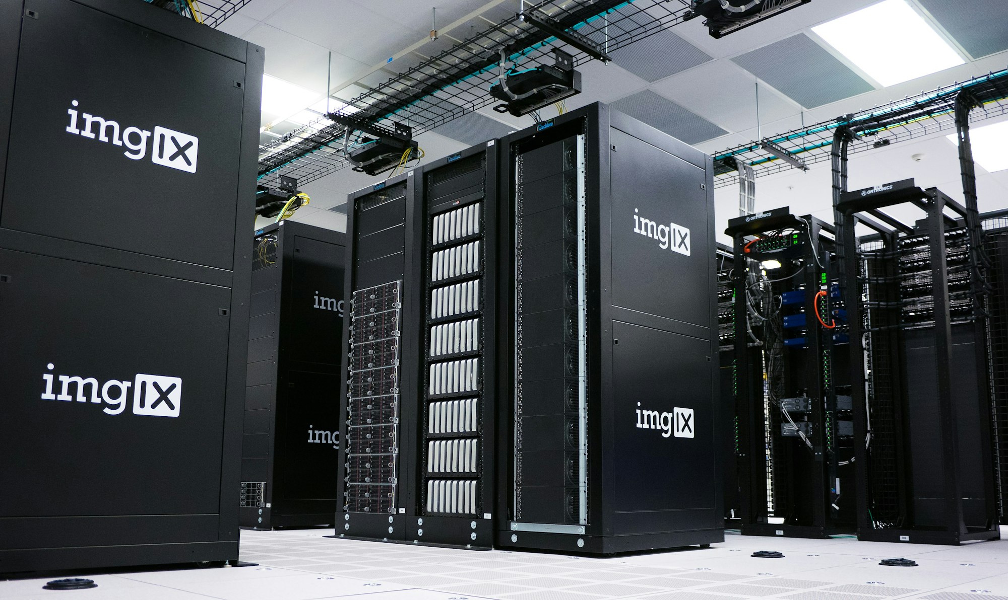
Photo: imgix / Unsplash
A backup-power claim becomes easier to understand when its boundary is drawn on a simple diagram. Keeping a server powered is different from keeping an entire service available, and neither statement describes every possible interruption.
The operating distinction
Electricity reaches the application through equipment with different jobs. A battery may support the server while a generator starts, yet the cooling controls, network equipment or building pumps could depend on another circuit. If any necessary part loses power, the application can stop even when its own power supply remains healthy.
The boundary also determines what an availability statement leaves out. A supplier may describe its equipment accurately while a customer reasonably hears a promise about the application. Those interpretations should be reconciled before a purchase or acceptance discussion.
A practical example
Consider a hypothetical hall with battery-backed racks and a cooling pump outside that protected boundary. A short interruption could leave the processors running while coolant circulation stops. The useful question is how the whole service behaves during that interval, rather than whether the rack has a battery.
Questions worth asking
An availability promise becomes clearer when the protected equipment and the promised user outcome are named together. Otherwise different parties can agree on the words while assuming different boundaries around the service.
- Which supporting systems sit outside the protected power boundary?
- What happens while the system transfers between power sources?
- Which test demonstrates the claimed application-level behavior?
What the evidence supports
A drawing is not proof of performance. Actual protection depends on the installed arrangement, controls, maintenance state and tests. Two facilities using the same redundancy label can have different dependencies and different opportunities for a shared failure.
One useful reading exercise is to trace an ordinary user request through the drawing and mark every system it needs. Then consider an interruption at each boundary. This is a discussion exercise, not permission to disconnect equipment. It helps reveal which claims depend on assumptions that have not yet been stated and which supporting systems need evidence of their own before the broader service claim can be understood.
Define the service first, then examine the electrical and mechanical chain that keeps that service running.
Quick check
How much did you catch? Tap a question to see the answer.
1. Is keeping a server powered the same as keeping a service available?
Answer: No. Cooling, networking and building systems can sit on other circuits.
2. What helps make a backup-power claim clear?
Answer: Drawing its boundary on a simple diagram.
3. What can happen if a cooling pump sits outside the protected boundary?
Answer: Processors keep running while coolant circulation stops.
Going Deeper: Drawing the Diagram Step by Step
The exercise described above works best with a plain sheet of paper and a simple method. Here is one way to build the drawing for a hypothetical service before any comparison of backup power begins.
- Name the service outcome. Write one sentence at the top describing what users must be able to do, for example “customers can submit and receive answers within the agreed response time.” Everything else on the page exists to support that sentence.
- List the systems the request touches. Servers, storage, network switches, firewalls, the cooling loop serving those racks, the controls that run the cooling, and any building systems such as pumps or ventilation that the room depends on.
- Mark each system’s power source. Note which ones sit on battery-backed circuits, which rely on generator support only, and which run on ordinary utility power.
- Draw the boundary. Circle everything protected by the backup arrangement under discussion. Anything outside the circle is a dependency the claim does not cover.
- Walk through the transfer. For each system, ask what happens in the seconds between a utility interruption and the backup source taking over, and again when power returns.
- Note the evidence. Beside each system, write what test, document or record shows how it behaves. Blank spaces become the questions to ask.
Why the transfer interval deserves its own line
Batteries and generators do different jobs on different timescales. The battery carries the load immediately; the generator needs time to start and stabilize. Equipment that rides through the first interval may still be affected if it loses support during the second, or if controls reset when the source changes. Writing the sequence down makes those moments visible instead of assumed.
Common Gaps the Diagram Tends to Reveal
- Cooling controls on a separate circuit. Chillers or pumps may be backed up, but the controllers that tell them what to do might not be.
- Network equipment outside the protected room. A switch or router in another closet can become the single point that takes the service offline.
- Shared upstream components. Two “redundant” paths that pass through one panel, one transfer switch or one fuel supply can fail together.
- Monitoring that depends on the thing it monitors. If alarms run through systems that lose power, operators may not learn of a problem until users do.
- Restart behavior. Some equipment does not return to normal operation automatically when power is restored and may need manual steps.
Questions to Bring to a Supplier or Facility Conversation
- Which of the systems on our drawing does your claim cover, and which does it exclude?
- Is the stated availability measured at the equipment, the room or the service?
- What recent tests exercised the full transfer sequence, and what did they show?
- How are maintenance periods handled, when part of the protection may be out of service?
- Who is responsible for dependencies that sit between your scope and ours?
Questions Readers Ask
Is a redundancy label enough to compare two facilities? As noted above, the same label can describe different arrangements. The drawing and the evidence behind it are what make a comparison meaningful.
Who should draw the diagram? Ideally the people responsible for the service and the people responsible for the facility, together, so that assumptions on both sides end up on the same page.
Does this apply to small server rooms too? Yes. A single rack with a battery unit in an office can still depend on an unprotected air conditioner or network closet, so the same drawing exercise is useful at any scale.
How often should it be updated? Whenever equipment, layout or the service itself changes. A drawing that no longer matches the installed arrangement can be more misleading than none at all.
AI infrastructure explainers and news on iPhone, iPad and Apple Watch.
Power & Grid
FERC’s Large-Load Orders: The November 16 Grid Deadline Behind the AI Build-Out
FERC told all six grid operators it regulates to justify or rewrite their rules for connecting data centers and other large loads. After extensions, the answers are due November 16. Here is what to watch.
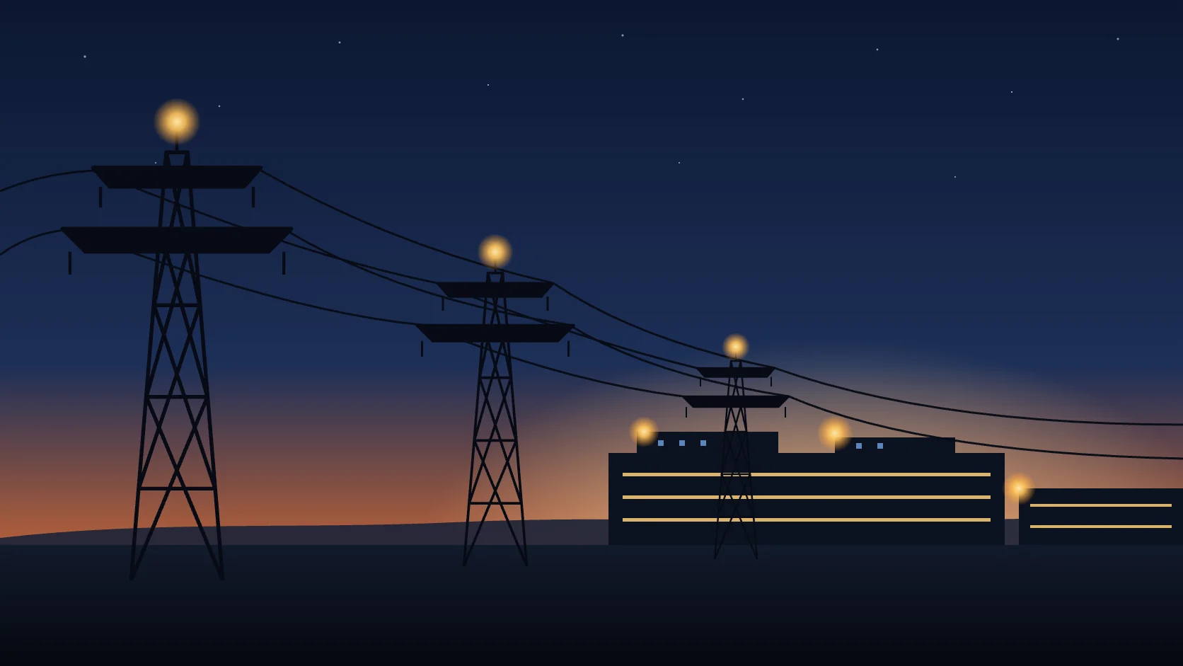
For most of the AI build-out, the hard question about a new data center has been about hardware: can the operator get the accelerators, the transformers and the cooling equipment? A slower question sits underneath all of them. Who decides how a 300-megawatt customer connects to the transmission grid, how long the study takes, and who pays if the project never arrives?
On June 18, 2026, the Federal Energy Regulatory Commission put that question to every grid operator it regulates. It issued six show cause orders, one each to PJM, MISO, SPP, CAISO, ISO New England and NYISO. Each order tells the operator and its transmission owners to either prove their current rules for large loads are just and reasonable or file new ones. After extensions, the responses are now due on November 16, 2026, for five of the six regions and November 20 for SPP.
This article explains what FERC asked for, where each step stands, and what the filings will tell readers following AI infrastructure.
How the grid got here
Generators that connect to the transmission grid have long had a federal process: a queue, studies and a standard agreement. Large consumers of electricity mostly did not. A new factory or data center usually connected through its local utility under rules set largely by states. That arrangement worked when a large industrial customer meant tens of megawatts. It strains when single campuses ask for hundreds of megawatts, sometimes with their own generation on site.
In October 2025 the Secretary of Energy used his authority under the Department of Energy Organization Act to send FERC an advance notice of proposed rulemaking on large-load interconnection, opened as Docket No. RM26-4-000. FERC says its staff reviewed more than 3,500 pages of public comments. Rather than issue a single national rule, the Commission chose tailored orders under Section 206 of the Federal Power Act, region by region. The rulemaking docket remains open.
FERC staff’s explainer describes the orders as covering facilities with maximum demand of at least 20 megawatts. They build on two earlier actions: a December 2025 order directing PJM to adopt transparent tariff rules for load co-located with generation, and FERC’s approval of SPP’s High Impact Large Load process.
The five issues every region must answer
Each order is tailored to its region, but all six identify the same five areas for reform:
- Faster, clearer study processes. A defined application path for large loads with accelerated study timelines, including evaluation of grid-enhancing and alternative transmission technologies.
- No cost shifting. Rules that keep upgrade costs for new large loads from landing on other customers, and public transparency into what those upgrades cost.
- Co-location and behind-the-meter generation. Clear tariff rules for data centers built next to, or behind the meter of, a power plant.
- Services for flexible loads. New transmission products, such as non-firm or contract-demand service, for customers willing to curtail during grid stress.
- Studying generation and load together. A process to study new generation alongside the nearby or co-located load it is built to serve.
The second item may matter most for public acceptance. FERC preliminarily found that operators do not publicly post enough data on the upgrades and costs needed to serve new large loads. The remedies it floated include posting each upgrade’s scope, cost and cost assignment, plus a central cost-transparency page on each operator’s website. FERC also asked whether operators should adopt standard cost recovery agreements among the grid operator, the transmission owner and the large customer. Those agreements would protect other ratepayers if a project is canceled or leaves early.
Two limits are easy to miss. The findings are preliminary, and FERC staff note the orders do not impose new transmission rates. The orders also apply going forward. FERC said they are not meant to disturb existing agreements or negotiations already near completion.
Where the clock stands
The orders set two deadlines. Within 30 days, each region had to file an informational report on how it will keep enough generation for existing and new large loads. MISO, for example, filed its report on July 20. Within 60 days, each region had to file its tariff response, unless it asked FERC to pause the case.
The operators asked for that pause, and FERC staff now list November 16 as the response date for five regions and November 20 for SPP. CAISO’s August 3 motion requested a 90-day abeyance so it could build a tailored filing with its transmission owners through an accelerated stakeholder process. MISO and its transmission owners filed a similar request the same day, and MISO reports that FERC granted it on August 14. In MISO’s case, responses are now due November 16 and answers to those responses December 16.
The pause has limits. CAISO’s motion notes that FERC said it would not grant abeyances reflexively. FERC capped them at 90 days and said it would look with great disfavor on requests to extend them further. That makes November 16 a firmer date than regulatory deadlines often are.
Some regional work is moving on a parallel track. CAISO’s published schedule takes its large-load proposal to its Board of Governors on October 28, ahead of the FERC filing. MISO separately filed interconnection reliability requirements for large loads on August 28, asking for a December 4 effective date.
What the filings will reveal
The responses will be long and technical. A handful of questions will say most of what matters about how quickly new AI capacity can connect, and on what terms.
- Study timelines. Does each region commit to a defined number of days for a large-load study, and what readiness deposits or milestones must a project show to keep its place?
- Interim service. Can a data center take non-firm or as-available service while network upgrades are built, and how often could that service be curtailed?
- Financial security. How much must a large customer commit up front, and what happens to that money if the project shrinks or is canceled?
- Co-location rules. How will regions treat a campus that sits beside a power plant, and what share of grid costs does it carry?
- Cost posting. Will upgrade costs be published per project, so state regulators and the public can see who pays?
The answers will likely differ by region. A region that offers a fast, well-defined path with clear collateral rules may attract projects that can meet those terms. A region whose answers stay open-ended may keep seeing projects wait in queues and bilateral negotiations. Readers should treat any claimed speed-up with care until the tariff language is approved and the first projects move through it.
The orders also leave a gap. Utilities outside the six RTO and ISO regions, including much of the Southeast and West, are not directly covered. FERC Chairman Laura Swett encouraged those transmission providers to pursue similar reforms through their own filings. ERCOT, which runs most of the Texas grid, is not subject to the orders.
Why this belongs on an AI-infrastructure watch list
BOSSTOX has covered the physical limits on AI capacity: transformer lead times, transmission and local grid upgrades, behind-the-meter generation and on-site storage. The FERC proceeding is the rulebook that ties those pieces together. It decides how a project enters the grid, which upgrades it triggers, and who carries the risk if forecast demand does not arrive.
The dates to watch are concrete: CAISO’s board meeting on October 28, the six responses due November 16 and 20, answers due in mid-December, and the FERC orders that follow. BOSSTOX will review the filings once they are posted and report what each region actually committed to.
This article is general information about a regulatory proceeding. It is not investment, legal or regulatory advice. Filing dates come from FERC and grid-operator documents and may change; check the dockets for the latest.
Sources
- FERC, “FERC Launches Aggressive Targeted Action to Speed Large Load Integration,” June 18, 2026: ferc.gov
- FERC Office of Public Participation, “Cost Transparency and Customer Protection Initiatives in FERC’s June 2026 Show Cause Orders for Large Load Interconnections”: ferc.gov
- California ISO, “Motion for Abeyance,” Docket No. EL26-71-000, August 3, 2026: caiso.com
- MISO, “Large Load Working Group FERC Status Report,” September 9, 2026: misoenergy.org
- Akin Gump, “FERC Issues Landmark Show Cause Orders on Large Load Interconnection,” June 2026: akingump.com
BOSSTOX Research articles are drafted with AI assistance and reviewed by our editors before publication. See our editorial standards.

A Coolant Distribution Unit Needs Its Own Power-Loss Story

The Control Plane Can Be a Shared Dependency Across Separate Systems

A Maintenance Window Changes the Meaning of Redundancy

Remote Support Depends on More Than a Telephone Number

Transformer Lead Times Are Becoming a Data-Center Schedule Risk

Gas Turbines on Data-Center Campuses

Water Use and Dry Coolers: The Tradeoff AI Sites Cannot Avoid

Battery Storage at AI Sites
A Coolant Distribution Unit Needs Its Own Power-Loss Story
The Control Plane Can Be a Shared Dependency Across Separate Systems
A Maintenance Window Changes the Meaning of Redundancy
Remote Support Depends on More Than a Telephone Number
-
 Power & Grid1 month ago
Transformer Lead Times Are Becoming a Data-Center Schedule Risk
-
 Power & Grid1 month ago
Gas Turbines on Data-Center Campuses
-
 Cooling2 months ago
Water Use and Dry Coolers: The Tradeoff AI Sites Cannot Avoid
-
 Power & Grid1 month ago
Battery Storage at AI Sites
-

 Compute & Silicon1 month ago
GPU Supply Chains: How AI Hardware Gets Made, Moved, and Bottlenecked
-

 Power & Grid4 weeks ago
FERC’s Large-Load Orders: The November 16 Grid Deadline Behind the AI Build-Out
-

 Capital & Backlog4 weeks ago
AI Infrastructure’s Rough Week: Chips Fall 6.7% as Meta Lifts Capex Floor
-

 Cooling4 weeks ago
Liquid-Cooling Leak Detection and Reliability